

Well Drilling, Mud and Sand Separator, ANSYS Fluent CFD Simulation Training
Price: $28
The present problem simulates well drilling and sludge separation using ANSYS Fluent software.
Well Drilling, Mud and Sand Separator, ANSYS Fluent CFD Simulation Training
Price: $28
The present problem simulates well drilling and sludge separation using ANSYS Fluent software.

Well Drilling Project Description
The present problem simulates well drilling and sludge separation using ANSYS Fluent software. In this simulation, a cylindrical hole is considered a well, inside which a rotating body in the shape of a cylinder is placed. Inside the cavity, a Non-Newtonian material for drilling operations flows; So that the mud particles inside it are mixed. With its rotational motion at 100 rpm, this rotating cylindrical body can separate the mud particles mixed in the non-Newtonian fluid and raise them. Therefore, the Eulerian multiphase model has been used to define the flow in the well. The primary phase of this multiphase flow is related to the same non-Newtonian fluid called CMC, and its second phase is related to mud particles called drilling.
Eulerian multiphase model in cases such as concentration of more than 10 percent of dispersed particles in the base fluid, pneumatic transitions for liquid and solid flows, the slurry flows in a liquid and solid, deposition as two-phase liquid and solid flows, etc. is used. In this simulation, the base fluid within the computational area has a volume fraction equal to 0.87, and the mud solution particles have a volume fraction equal to 0.13. Fluids are also divided into two categories of Newtonian and non-Newtonian fluids in terms of viscosity. The viscosity of a fluid is a parameter that indicates the resistance of that fluid to flow. Newtonian fluids follow Newton's law of viscosity (shear stress in a Newtonian fluid changes linearly with strain rate).
Project Description
Also, their viscosity depends only on the temperature and pressure of the fluid, and by applying force to them in constant temperature and pressure, their viscosity does not change; Non-Newtonian fluids, on the other hand, are fluids that do not follow Newton's law of fluids, and their viscosity changes with the application of force. The fluid CMC as the primary phase has a density of 1271.477 kg.m-3, and its viscosity is defined as non-Newtonian, which is according to the Herschel-Bulkley rule; While the soluble particles of mud in the Non-Newtonian fluid also have a density equal to 2000 kg.m-3 and a viscosity equal to 0.00111 kg.m-1.s-1.
Geometry & Mesh
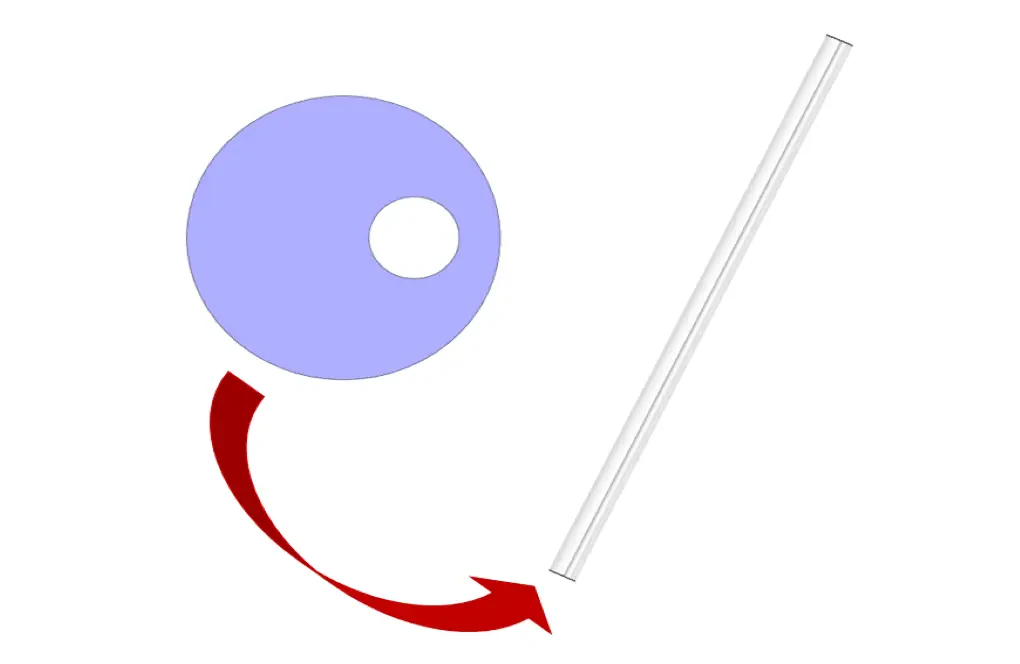
The present model is designed in three dimensions using Design Modeler software. The model is related to two eccentric cylindrical walls. These two cylinders have a length equal to 10 m, and the diameter of the inner cylinder is equal to 0.128 m, and the diameter of the outer cylinder is equal to 0.444 m.
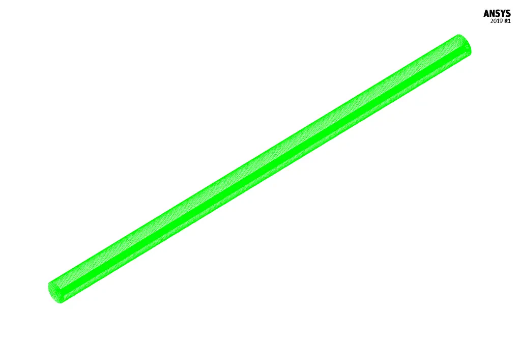
We carry out the model's meshing using ANSYS Meshing software. The mesh type is unstructured. The element number is 179820. The following figure shows the mesh.
CFD Simulation
We consider several assumptions to simulate the present model:
- We perform a pressure-based solver.
- The simulation is unsteady.
- The gravity effect on the fluid is equal to -9.81 m.s-2. So that according to the angle of 30 degrees of the model with the direction of gravity, the amount of gravity acceleration is equal to 4.9 and 8.5 in the X and Z directions, respectively.
The following table represents a summary of the defining steps of the problem and its solution:
| Models | ||
| Viscous | k-omega | |
| k-omega model | standard | |
| Multiphase Model | Eulerian | |
| number of eulerian phases | 2 (cmc & drilling) | |
| formulation | implicit | |
| Boundary conditions | ||
| Inlet | Velocity Inlet | |
| gauge pressure | 0 Pascal | |
| velocity magnitude - cmc | 0.357 m.s-1 | |
| volume fraction - cmc | 0.87 | |
| velocity magnitude - drilling | 0.357 m.s-1 | |
| volume fraction - drilling | 0.13 | |
| Outlet | Pressure Outlet | |
| gauge pressure | 0 pascal | |
| Inner Wall | Wall | |
| wall motion | moving wall | |
| motion | rotational (z-axis) | |
| speed | 100 rpm | |
| Outer Wall | ||
| wall motion | stationary wall | |
| Methods | ||
| Pressure-Velocity Coupling | Phase Coupled SIMPLE | |
| Pressure | PRESTO | |
| momentum | first order upwind | |
| turbulent kinetic energy | first order upwind | |
| specific dissipation rate | first order upwind | |
| volume fraction | first order upwind | |
| Initialization | ||
| Initialization methods | Standard | |
| gauge pressure | 0 Pascal | |
| velocity - cmc | 0.357 m.s-1 | |
| velocity - drilling | 0.357 m.s-1 | |
| volume fraction - drilling | 0.1 | |
Well Drilling Results & Discussions
At the end of the solution process, two-dimensional and three-dimensional contours related to pressure, CMC velocity, drilling speed, CMC volume fraction, drilling volume fraction, turbulent kinetic energy are obtained.