

Air Intake of Gas Turbine Considering Fogging System, CFD Simulation ANSYS Fluent Training
Price: $12
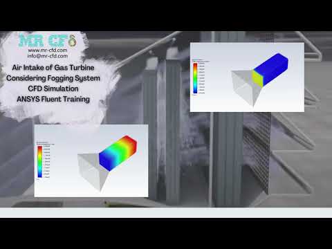
In this project, a part of the air intake duct of the gas turbine is simulated, considering the fogging system via Ansys Fluent.
Air Intake of Gas Turbine Considering Fogging System, CFD Simulation ANSYS Fluent Training
Price: $12
In this project, a part of the air intake duct of the gas turbine is simulated, considering the fogging system via Ansys Fluent.
Introduction
The gas turbine efficiency is highly dependent on the inlet temperature supplied by ambient air. Thus, by decreasing the inlet temperature, the gas turbine performance could be significantly improved. The fogging system is one of the best solutions that work by injecting billions of water droplets into the inlet duct and causing a decrease in intake temperature by evaporating.
Air Intake of Gas Turbine Considering Fogging System Problem Description
In this project, a part of the air intake duct of the gas turbine is simulated, considering the fogging system. Air enters the first section of the duct at 2m/s velocity magnitude and encounters millions of water droplets after passing through a nozzle. The aim of the study is to investigate the effect of fogging system on temperature. We have used discrete phase model (DPM) and Species Transport Model in this simulation.
Geometry & Mesh
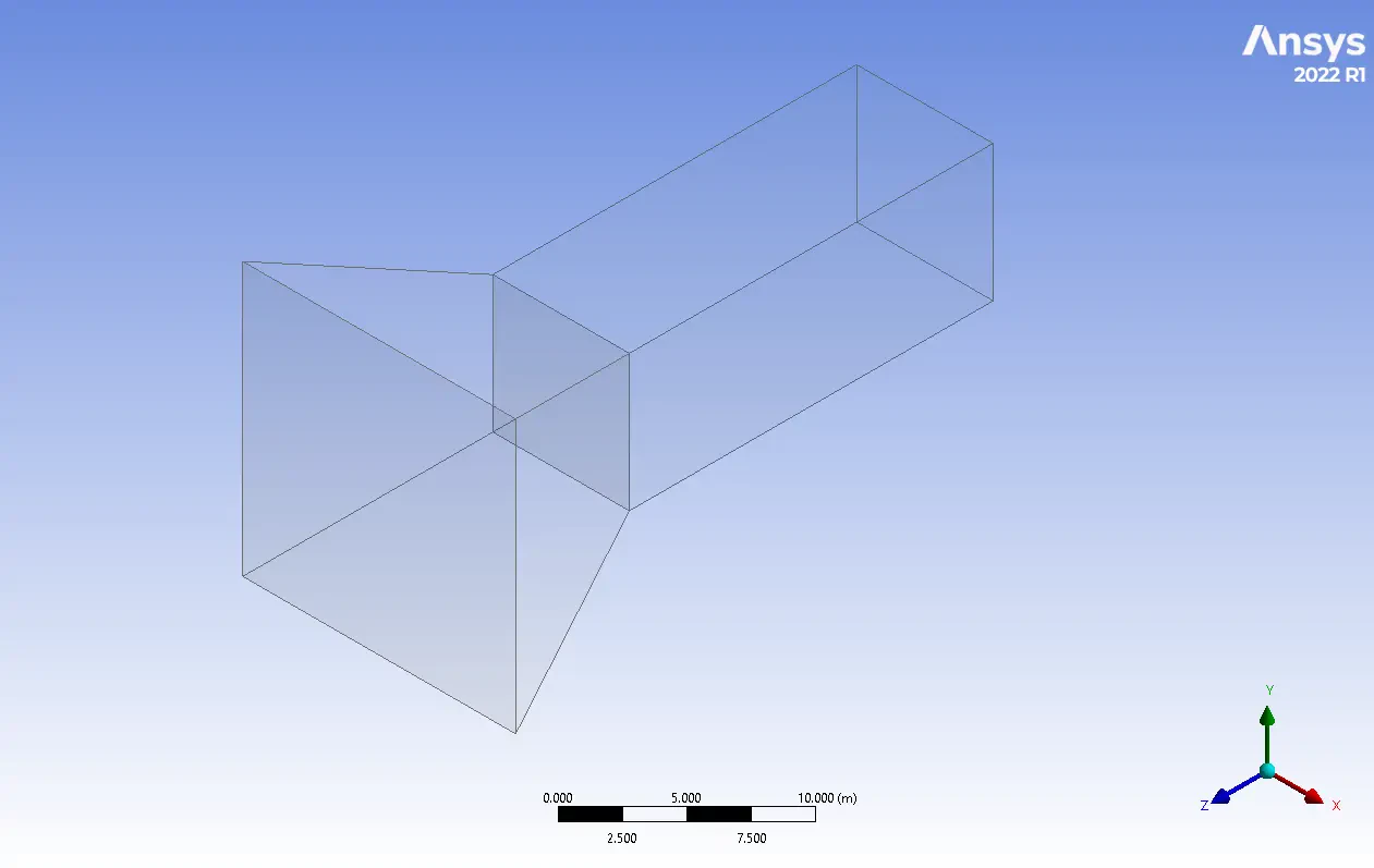
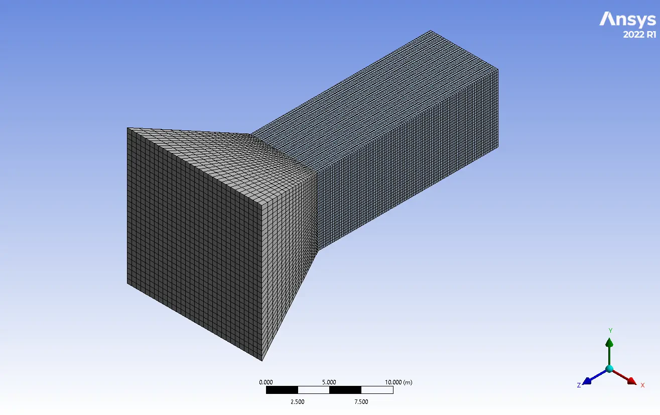
The 3D geometry is modeled in Ansys Design Modeler software. A 15*15m duct is connected to a 7.5*7.5m duct (figure 1). Also, the mesh grid is carried out using Ansys Meshing software. Furthermore, a structured grid is generated to keep computational costs at optimal conditions. Therefore 108000 elements established the fluid domain.
CFD Simulation
Several assumptions have been considered to simulate the fogging system in the gas turbine air intake, including:
- The simulation is Transient to investigate the fogging system's influence over time.
- The pressure-based solver type is used due to the incompressibility of the working fluid.
- Gravitational acceleration effects are applied in the –y-direction.
The following table represents a summary of the solution:
| Models(Viscous) | ||||
| Viscous | K-epsilon | Standard | ||
| Species | Model | Species Transport | ||
| Discrete phase Model | Interaction | Interaction with continuous phase | ||
| DPM iteration interval | 10 | |||
| Particle Treatment | Unsteady Particle Tracking Track with fluid flow time step | |||
| Injections | Particle Type: Droplet | |||
| Injection Type: Surface Material: Water-liq Evaporating Species: h2o Diameter: 1e-5 Temperature: 283K Velocity Magnitude: 1m/s Total Flow Rate: 5kg/s | ||||
| Materials | ||||
| Fluid | Definition method | Fluent database | ||
| Material name | Air | |||
| Droplet Particle | Water-liq | |||
| Cell zone condition | ||||
| Material name | Mixture-template | |||
| Boundary condition | ||||
| Inlet | Type | Velocity inlet | ||
| Velocity magnitude | 2m/s | |||
| Turbulent intensity | 5% | |||
| Turbulent viscosity ratio | 10 | |||
| Outlet Wall | Type | Pressure-outlet | ||
| Gauge Pressure | 0 | |||
| Type | Wall (Stationary – No-slip condition) | |||
| Solver configuration | ||||
| Pressure-velocity coupling | Scheme | SIMPLE | ||
| Spatial Discretization | Gradient | Least squares cell-based | ||
| Pressure | Second order | |||
| Momentum | Second-order upwind | |||
| Turbulent kinetic energy | First-order upwind | |||
| Turbulent dissipation rate | First-order upwind | |||
| Energy | First-order-upwind | |||
| H2o | First-order-upwind | |||
| Initialization | Initialization methods | Standard Initialization | ||
| Run Calculation | Time step size | 0.01 | ||
| Max iteration/time step | 20 | |||
Air Intake of Gas Turbine Considering Fogging System Results
After the simulation process, 2d & 3d contours are extracted. As seen in the outlet's temperature report, the droplets could be evaporated by receiving heat from the air due to the temperature gradient. As a result, the temperature falls to 306.5K. Note that, in the industries, the air intake ducts are designed giant that could pass a large mass flow. Besides, the total number of droplets is higher, but considering the study aim, we have simplified it to reduce computational costs.