

External Flow around an Atrium CFD Simulation, ANSYS Fluent Training
Price: $12
The present problem simulates the external airflow through an atrium.
External Flow around an Atrium CFD Simulation, ANSYS Fluent Training
Price: $12
The present problem simulates the external airflow through an atrium.
Externa Airflow over an Atrium Project Description
The present problem simulates the airflow through an atrium by ANSYS Fluent software. The history of these atriums originates from the architecture of ancient Roman houses, and its modern models in recent centuries are multi-story and have a glass roof and a set of windows, often immediately located after the main entrances of the buildings. This part of the building is used to provide the necessary light for the interior of the building as well as the ventilation of the building.
Atriums basically work with two natural phenomena, including the greenhouse effect and the chimney effect. In the present study, the area around the atrium is considered to be that the airflow enters it horizontally at a rate of 8 m.s-1 at a pressure of 101325 Pa and hits the walls of the atrium. The aim of this study is to investigate the behavior of airflow around the walls of the atrium after colliding with them and to investigate the distribution of pressure and velocity of the flow around the atrium.
Atrium Geometry & Mesh
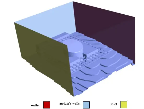
The present 3-D model is drawn using the Design Modeler software. The present model consists of a very large area in the form of a rectangular cube with dimensions of 3.35 m ⨯2.21 m ⨯3.9 m and an atrium inside the interior of this area. The following figure shows a view of the geometry.
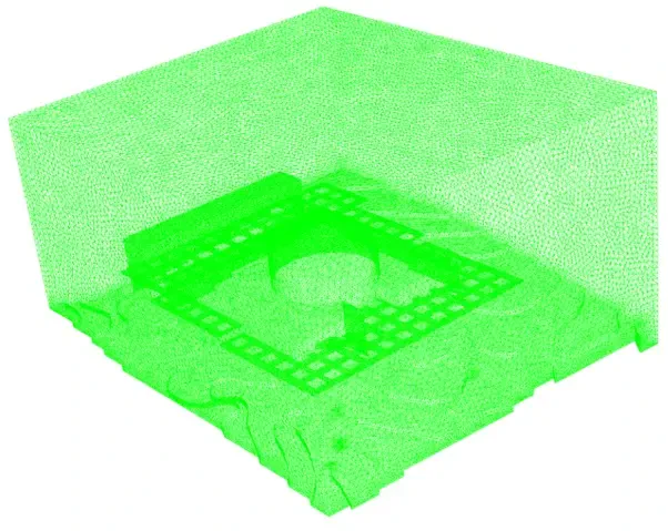
The meshing of the model has been done using ANSYS Meshing software and the mesh type is unstructured. The element number is equal to 1953066, and the cells adjacent to the structures are smaller and more accurate. The following figure shows a view of the mesh.
CFD Simulation
To simulate the present model, several assumptions are considered:
- A pressure-based solver has been performed.
- The simulation is steady-state.
- The effect of gravity on the fluid is not considered.
A summary of the steps for defining the problem and its solution is given in the table:
| (atrium) | Models | |
| Viscous model | k-epsilon | |
| k-epsilon model | RNG | |
| near-wall treatment | standard wall function | |
| (atrium) | Boundary conditions | |
| Inlet | Velocity inlet | |
| velocity magnitude | 8 m.s-1 | |
| Outlet | Pressure outlet | |
| gauge pressure | 0 Pascal | |
| Sidewalls and building | Wall | |
| Wall motion | stationary wall | |
| (external flow) | Solution Methods | |
| Pressure-velocity coupling | SIMPLE | |
| Spatial discretization | pressure | second-order |
| momentum | second-order upwind | |
| turbulent kinetic energy | first-order upwind | |
| turbulent dissipation rate | first-order upwind | |
| (external flow) | Initialization | |
| Initialization method | Standard | |
| gauge pressure | 101325 pascal | |
| z-velocity | 8 m.s-1 | |
| x-velocity, y-velocity | 0 m.s-1 |
Results
After the solution process is complete, two-dimensional and three-dimensional contours related to pressure, velocity, as well as path lines and two-dimensional and three-dimensional velocity vectors are obtained. The contours, path lines, and two-dimensional vectors are plotted in the XY section. Also, the pressure distribution contour on the wall surfaces is obtained.