

Pollution in a Real Urban Zone, ANSYS Fluent CFD Simulation Training
Price: $20
- The problem simulates a mass fraction of carbon dioxide changes as the pollutant in an urban street by ANSYS Fluent software.
- The present model is three-dimensional and is drawn using the Design Modeler software.
- The meshing is done using ANSYS Meshing software. The element number is 4137570.
- Simulation using the Species Transport solves a Transport Equation for each component of the pollution mixture.
- The simulation is Transient since the goal is to study changes in carbon dioxide concentration over time.
Pollution in a Real Urban Zone, ANSYS Fluent CFD Simulation Training
Price: $20
- The problem simulates a mass fraction of carbon dioxide changes as the pollutant in an urban street by ANSYS Fluent software.
- The present model is three-dimensional and is drawn using the Design Modeler software.
- The meshing is done using ANSYS Meshing software. The element number is 4137570.
- Simulation using the Species Transport solves a Transport Equation for each component of the pollution mixture.
- The simulation is Transient since the goal is to study changes in carbon dioxide concentration over time.

Pollution Dispersion CFD Simulation
Urban environments are the most important context of life, and in most developing countries the status of air pollution is getting worse day by day, although technological improvements have played an important role in reducing air pollution emissions. Due to the increasing demand for transportation, it will remain a challenge. Simulation using the Species Transport solves a Transport Equation for each component of the pollution mixture. The purpose of the analysis is to calculate the amount of CO2 pollution dissipated in an urban zone.
Project Description
The problem simulates changes in the mass fraction of carbon dioxide on an urban street by ANSYS Fluent software. To simulate this model, a 0.1 m height area should be considered as a source of carbon dioxide pollutants on the street from the urban domain. In fact, the main purpose of the current simulation is to investigate the effect of free airflow on the amount of CO2 produced by car exhaust. Therefore, an integrated carbon-dioxide production area is defined as a source of mass production on a city street.
Free airflow enters the area around an urban environment at a velocity of 0.2 m.s-1 and a temperature of 300 K. Since the CO2 and airflow are modeled, the Species Transport model has been used; Thus, these gaseous species include air and CO2. The amount of carbon dioxide produced in the definition area on the street is 4 kg.m-3.
Geometry & Mesh
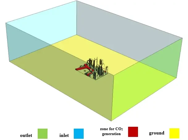
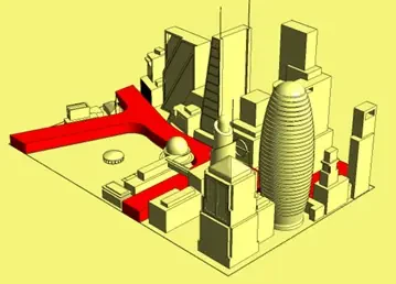
The present model is three-dimensional and is drawn using the Design Modeler software. This model is a set of structural elements consisting of several building blocks and a street belonging to a city. An area in the shape of a rectangular cube with dimensions of 9 m ⨯ 13 m ⨯ 4 m is designed around this urban complex. The airflow inlet is selected in three lateral sections of this area. There is also a 0.1 m high area on one of the city streets. The following figure shows a view of the geometry.
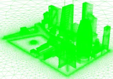
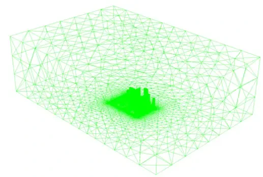
The meshing is done using ANSYS Meshing software. The mesh type is unstructured and the element number is 4137570. Grids are smaller in the areas adjacent to the internal boundaries and have higher accuracy. The following figure shows a view of the mesh.
Pollution CFD Simulation
To simulate the present model, several assumptions are considered:
- The solver is pressure-based.
- The simulation is transient since the goal is to study changes in carbon dioxide concentration over time.
A summary of the steps for defining the problem and its solution is given in the table:
| Models (UHI) | ||
| Viscous model | k-epsilon | |
| k-epsilon model | standard | |
| near-wall treatment | standard wall function | |
| species transport model | ||
| species | air, CO2 | |
| Energy | on | |
| Boundary conditions | ||
| Inlet | Velocity inlet | |
| velocity magnitude | 0.2 m.s-1 | |
| temperature | 300 K | |
| CO2 mass fraction | 0 | |
| Outlet | Pressure outlet | |
| gauge pressure | 0 Pascal | |
| Walls | Wall | |
| wall motion | stationary wall | |
| heat flux | 0 W.m-2 | |
| CO2 mass fraction | zero diffusive flux | |
| Solution Methods (UHI) | ||
| Pressure-velocity coupling | SIMPLE | |
| Spatial discretization | pressure | second-order |
| momentum | second-order upwind | |
| turbulent kinetic energy | first-order upwind | |
| turbulent dissipation rate | first-order upwind | |
| energy | second-order upwind | |
| CO2 | second-order upwind | |
| (UHI) | Initialization | |
| Initialization method | Standard | |
Results
At the end of the solution process, two-dimensional contours of pressure, temperature, velocity, air and CO2 mass fraction were obtained in the whole model environment. These two-dimensional contours are drawn in XY and YZ sections. Also, the three-dimensional contours related to pressure, temperature, velocity, air and CO2 mass fraction have been obtained in the area of the CO2 source term.
You can obtain Geometry & Mesh file, and a comprehensive Training Movie which presents how to solve the problem and extract all desired results.