

Splitter Erosion CFD Simulation Training using DPM by ANSYS Fluent
Price: $30
In this study, using the DPM (Discrete phase material) method, the effect of impurities in the working fluid on the splitter erosion was investigated.
Splitter Erosion CFD Simulation Training using DPM by ANSYS Fluent
Price: $30
In this study, using the DPM (Discrete phase material) method, the effect of impurities in the working fluid on the splitter erosion was investigated.

Splitter Introduction
A splitter is a device for uniformly distributing incoming fluid flow by placing outlets of the same shape and size. Using Splitter, in addition to evenly dividing the initial flow rate, can absorb the impurities with a filter and increase the purity of the outlet gas. The impact of impurities such as sand and oxides of various metals can lead to erosion overtime on the body of various equipment. Therefore, studying the effect of erosion on transmission pipelines and fluid flow distribution will be of particular importance.
Problem Description
In this study, using the DPM (Discrete phase material) method, the effect of impurities in the working fluid on the body gas splitter was investigated. The impurity gas entered vertically at a speed of 5 meters per second and was directed out through 3 outlets. Using Ansys Fluent software, the impurity distribution, concentration, adsorption, and reflection in the installed filters were observed. Different erosion models in the software help correctly predict the erosion effect according to different working conditions.
Splitter Geometry & Mesh
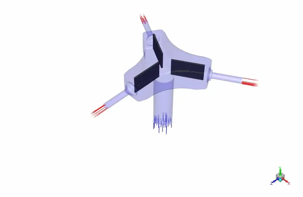
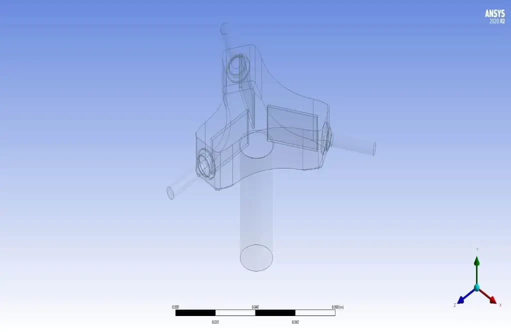
The designed geometry specifications include a gas splitter with three nozzles at the outlet. The inlet diameter of the mainstream is 1.6 cm, and the outlet nozzles' diameter is 0.3 cm. In addition, 2.5 cm long fins are located inside the geometry as a filter (Figure below). (Design Modeler software)
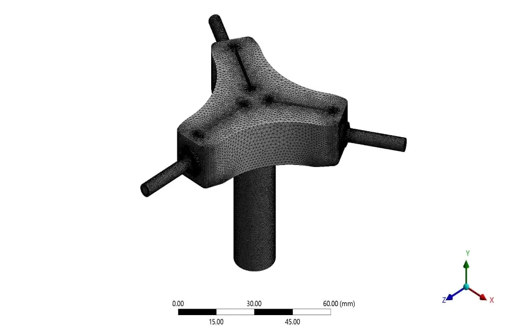
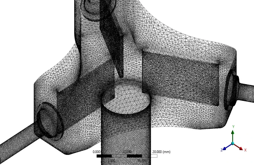
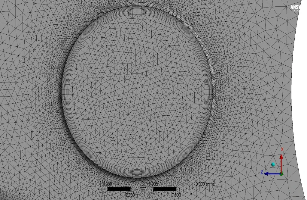
For grid generation, unstructured mesh with 2728426 elements in the ANSYS Meshing module was utilized. The curvature and proximity method focused on grid-sensitive areas like close to fins. Also, the boundary layer mesh next to the walls was used to satisfy the turbulence model Y+. The following figure shows the mesh generation for this problem.
Solver Setting
ANSYS Fluent software was used to solve the governing equations numerically. The problem is analyzed steady using the pressure-based method, and the gravitational effects were not considered. Also, for solving the above problem, RANS Includes discrete phase particles by integrating the force balance on the particles, which is written in a Lagrangian reference frame. This force balance equates the particle inertia with the forces acting on the particle.
Material Properties
Due to the high-speed internal flow in the computational domain, the natural gas density was assumed to be constant and thermodynamic characteristics such as viscosity and thermal conductivity of gas and impurity density were set.
Boundary Conditions and Solution CFD Methods
Also, The table below shows the characteristics and values of boundary conditions, along with the models and hypotheses.
| Material Properties (Erosion) | |||
| Natural gas | |||
| Amount | Fluid properties | ||
| 0.65 | Density (kg/m3) | ||
| 0.00013 | Viscosity (kg/m.s) | ||
| Inert-particle (impurities) | |||
| Amount | Fluid properties | ||
| 1600 | Density (kg/m3) | ||
| Discrete phase model (DPM) | |||
| Interaction with continuous phase (Erosion) | 10 continues phase iteration per DPM | ||
| Max step tracking | 50000 | ||
| Step length factor | 5 | ||
| Physical model | Erosion/Accretion Generic model Finnie Oka | ||
| Accuracy Control | 1e-5 | ||
| Max.Refinement | 20 | ||
| Tracking Scheme Selection: | Trapezoidal | ||
| Injection type: | Surface velocity inlet | ||
| Diameter Distribution: | uniform | ||
| Diameter: | 0.15mm | ||
| Total flow rate: | 0.04627kg/s | ||
| Drag law: | Spherical | ||
| Turbulent Dispersion: | Stochastic Tracking Discrete Random Walk Model Random Eddy Lifetime Number of Tries 10 Time Scale Constant 0.3 | ||
| The number of particles tracked: | 24900 | ||
| The number of particles trapped: | 8202 | ||
| The number of particles that escaped: | 16695 | ||
| Initialize: | standard | ||
| Boundary Condition (Erosion) | |||
| Type | Amount (units) | ||
| Velocity inlet | 5 m/s | ||
| pressure outlet (gauge pressure) | 0 pa | ||
| domain wall | |||
| Fin wall | trap | ||
| External domain wall | escape | ||
| Cell zone condition | |||
| Fluid | Natural gas | ||
| Turbulence models (Erosion) | |||
| K- | viscous model | ||
| Realizable | K- model | ||
| Enhanced-wall treatment | Wall function | ||
| Solution methods (Erosion) | |||
| SIMPLE | pressure velocity coupling | ||
| Standard | pressure | spatial discretization | |
| Second-order upwind | momentum | ||
| First-order upwind | turbulent kinetic energy | ||
| First-order upwind | turbulent dissipation rate | ||
Splitter Results
In this section, erosion models are first examined. The generic model can be used as an analytical equation for most cases because the material of impurities in this model is sand, which is present in most models. In model Finnie, which, like Oka and Mclaury models, uses an empirical correlation to predict erosion, it is mainly used for malleable materials. The Collision angle and velocity are effective. The model Oka considers the effect of wall hardness and may be more suitable for investigating the erosion of transmission pipes. Model Mclaury is used to study suspended solids in water and was unsuitable for the present case.
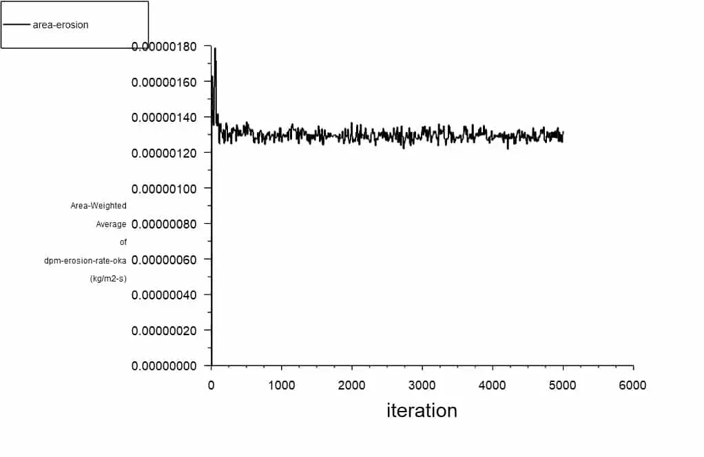
According to the above observations, by erosion contours of the splitter wall and examining the appropriate models, it was observed that in all models, the impact of particles on the upper wall due to high fluid velocity causes more erosion compared to other areas. The outlet nozzle walls are then subject to higher erosion. Oka Erosion diagrams have also been monitored during solution solving to better investigate the problem's convergence.
Results
Examination of the contour of the impurity concentration shows that in the output part of the Splitter, due to the high velocity of the downstream flow and the reduction of cross-section, the exit of solid particles were challenging, and the accumulation of particles in that part causes the concentration of impurities to increase. However, due to the placement of filtered fins, can increase the adsorption of impurity particles, which can be seen in the table above by trap and escape particle track.