

Wind Flow Over a Villa Building CFD Simulation
Price: Free
The present issue simulates the external flow of wind passing through the villa.
Wind Flow Over a Villa Building CFD Simulation
Price: Free
The present issue simulates the external flow of wind passing through the villa.
Wind Flow Over a Villa Building CFD Simulation, ANSYS Fluent Training
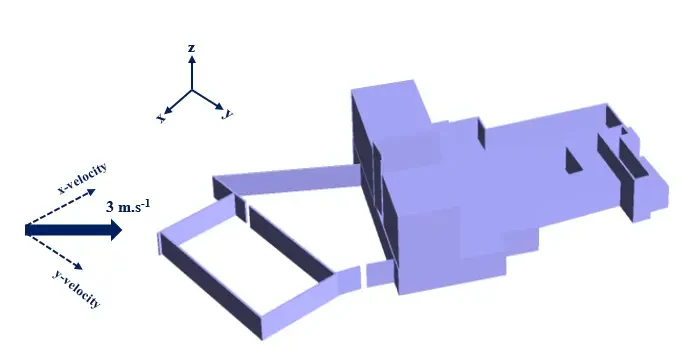
The present issue simulates the external flow of wind passing through the villa using ANSYS Fluent software. The geometry of the villa consists of several buildings and a special domain for the yard. The area around the villa is considered to be the airflow area. The wind speed is 3 m.s-1 and the ambient pressure is equal to the atmospheric pressure. The direction of airflow relative to the villa complex has a certain angle, so the velocity is divided into two values in the x and y coordinate directions.
The velocity vector angle is equal to 20 degrees relative to the y-axis, so the velocity vector in the y-direction is 3⨯cos(20º)=2.817 m.s-1 and is in the same direction as the Y vector, while the velocity vector in the x-direction is equal to 3⨯sin (20º) = 1.026 ms-1 and is in the opposite direction of the x-axis. The following figure shows a schematic of the problem model with Cartesian coordinates and wind direction.
Villa Building Geometry & Mesh
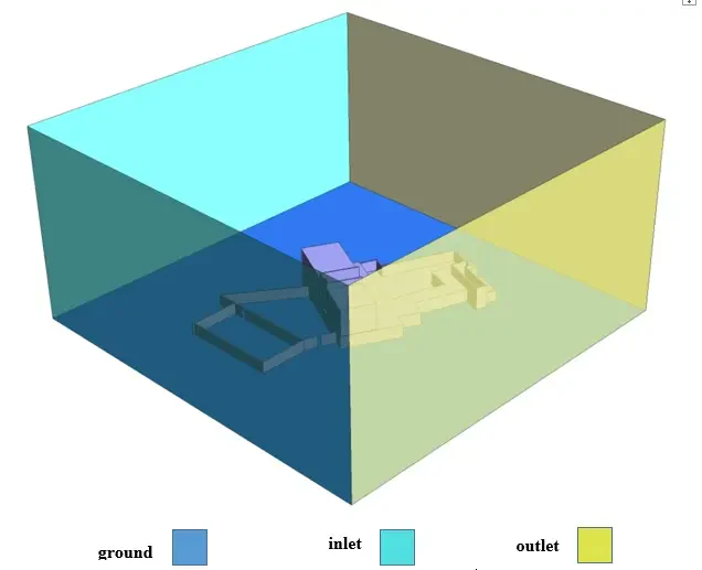
The present model is three-dimensional and is drawn using the SpaceClaim software. The current model consists of a villa complex and an airflow area. The villa complex consists of several courtyards and buildings. The area for the flow is in the form of a rectangular cube, and according to the angle of the wind, the lateral two sides of this area have been considered as the inlet boundaries of the wind flow and the two opposite plates as the outlet boundaries. The figure below shows a view of geometry.
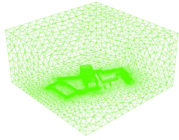
The meshing of the model has been done using ANSYS Meshing software and the mesh type is unstructured. The element number is 1825278 and the cells adjacent to the buildings are smaller and more accurate. The following figure shows a view of the mesh.
CFD Simulation
To simulate the present model, several assumptions are considered, which are:
- The Pressure-Based solver has been performed.
- Simulation has only been performed in a fluid state; heat transfer has not been discussed.
- The present simulation is steady-state.
- The effect of gravity on the fluid is not considered.
A summary of the steps for defining a problem and its solution is given in the table:
| Models | ||
| Viscous model | k-epsilon | |
| k-epsilon model | standard | |
| near-wall treatment | standard wall function | |
| Boundary conditions | (Wind Flow) | |
| Inlet | Velocity inlet | |
| x-velocity | -1.026 m.s-1 | |
| y-velocity | 2.817 m.s-1 | |
| z-velocity | 0 m.s-1 | |
| Outlet | Pressure outlet | |
| gauge pressure | 0 Pascal | |
| Walls | Wall | |
| Wall motion | stationary wall | |
| Solution Methods | (Wind Flow) | |
| Pressure-velocity coupling | SIMPLE | |
| Spatial discretization | pressure | second order |
| momentum | second order upwind | |
| turbulent kinetic energy | second order upwind | |
| turbulent dissipation rate | second order upwind | |
| Initialization | (Wind Flow) | |
| Initialization method | Standard | |
| gauge pressure | 0 pascal | |
| x-velocity | -1.026 m.s-1 | |
| y-velocity | 2.817 m.s-1 | |
| z-velocity | 0 m.s-1 |
Wind Flow Over a Villa Building Results
After the solution process is complete, two-dimensional and three-dimensional contours related to pressure and velocity, as well as two-dimensional and three-dimensional velocity vectors are obtained. Two-dimensional contours are assumed in all three sections, XY, YZ, and XZ.