

Marine Engineering: Beginner CFD Training Package
Price: $59
Marine Engineering: Beginner CFD Training Package is a ten-project introduction to marine and hydrodynamic simulation in ANSYS Fluent. Starting from ship-system internal airflow and progressing through hydrodynamic loading, free-surface waves, moving-body dynamic-mesh problems, and cavitating flows, it gives newcomers a hands-on, application-driven foundation in the CFD techniques behind modern marine, offshore, and ocean-energy engineering — one real engineering case at a time.
Marine Engineering: Beginner CFD Training Package
Price: $59
Marine Engineering: Beginner CFD Training Package is a ten-project introduction to marine and hydrodynamic simulation in ANSYS Fluent. Starting from ship-system internal airflow and progressing through hydrodynamic loading, free-surface waves, moving-body dynamic-mesh problems, and cavitating flows, it gives newcomers a hands-on, application-driven foundation in the CFD techniques behind modern marine, offshore, and ocean-energy engineering — one real engineering case at a time.
-
Engine Room Ventilation System of a Ship — ANSYS Fluent CFD Simulation Description This project presents a complete CFD simulation of a ship's engine room ventilation system — one of the most critical thermal-management challenges in marine engineering. Engine rooms house compressors, pumps, fans, diesel engines, and electric motors, all packed into a confined space and all generating significant heat. Without proper ventilation, equipment overheats, efficiency drops, and safety risks rise. In this project, you'll use ANSYS Fluent to simulate how injected cool air at 300 K distributes through the engine room and removes heat from the operating machinery, allowing you to evaluate ventilation effectiveness and identify hot spots. As the opening project of the Marine Engineering: Beginner CFD Training Package, it introduces the CFD workflow through a self-contained internal-airflow problem in a familiar marine setting. Methodology The 3D engine room geometry is imported and prepared in SpaceClaim, then meshed in ANSYS Meshing with an unstructured grid of roughly 706,000 cells to resolve the complex internal flow domain and its multiple equipment volumes. The energy equation is activated to capture the heat transfer, and the machinery is modeled as distributed heat generators through volumetric heat sources defined in the cell-zone conditions — 12,500 W/m³ for the diesel engines and 8,333.33 W/m³ for the electric motors. The marine-specific boundary conditions comprise a mass-flow inlet supplying 35 kg/s of air at 300 K and dual pressure outlets for natural exhaust. Appropriate turbulence and solver settings are chosen for this internal forced-convection ventilation problem. Analysis Post-processing produces temperature, velocity, and pressure contours, along with streamlines and velocity vectors that show how the cool air reaches the hot equipment surfaces. From these results you can evaluate ventilation effectiveness — identifying whether the cool air actually reaches the hottest machinery zones and where hot spots remain. The same CFD workflow built here — volumetric heat sources, forced ventilation, and internal recirculation — applies directly to engine rooms in submarines, ferries, cargo vessels, and offshore platforms, as well as to data centers and industrial machinery enclosures on land. By the end of this project, you'll be able to set up an internal forced-convection ventilation simulation, model machinery as volumetric heat sources, and interpret the flow and temperature fields to assess how effectively a confined marine space is cooled.
Lesson 1 16m 6s -
Offshore Pipeline Considering Hydrodynamic Force, ANSYS Fluent CFD Simulation Training Description This project simulates seawater flow around an offshore pipeline using ANSYS Fluent. Offshore pipelines are a core part of marine engineering, carrying oil, gas, and other resources across the seabed between platforms and shore. As seawater waves pass over these pipelines, they generate drag and lift forces on the pipe. To keep the line safe and stable, it must be positioned so that it experiences the lowest possible hydrodynamic loading, which makes this kind of analysis important for offshore pipeline design. The 2-D model was built in ICEM and consists of a rectangular seawater domain with a circular cross-section representing the pipe. Two key geometric parameters govern the study: the pipe diameter (D) and the gap between the bottom of the pipe and the seafloor (e), expressed through the e/D ratio. The pipe diameter is fixed at 0.4 m, and two cases are considered, e = 0.2 m and e = 0.1 m, giving e/D = 0.5 and e/D = 0.25. The seawater domain is 12 m long and 3.24 m high. The model was meshed in ICEM using a structured grid of 135,417 elements. To capture the flow accurately, the mesh is refined near the pipe: the circumference of the circular section is split into five segments, and the cells closest to the pipe are smaller and of higher quality. Simulation Methodology The main geometric variable in this study is the pipe-to-seafloor gap ratio (e/D). Because the seawater motion is wavy rather than steady, the inlet velocity is defined as a wave-flow equation through a UDF. Likewise, the pressure inside the seawater is measured relative to atmospheric pressure and varies with the wave motion, so the wave (ambient) pressure is also imposed through a UDF. In total, the inlet horizontal velocity, the relative wave pressure, the turbulent kinetic energy, and the turbulence dissipation rate are all defined as UDFs. The goal is to compare the hydrodynamic forces on the pipeline over one full wave period and identify the optimal configuration. The seawater wavelength (the distance between two wave peaks) is 163.20 m, with a corresponding period of 10.3 s, giving a wave angular frequency of 2π/Tw = 2π/10.3 ≈ 0.61 rad/s. The maximum velocity at a wave peak is 2.729 m/s, and k_m and ε_m denote the maximum turbulent kinetic energy and the maximum turbulence dissipation rate, respectively. In the wave-pressure equation, H is the wave height and d is the seawater depth. The term −z is the height of the water column at the point where the dynamic pressure is evaluated, and d − (−z) is the distance from that point down to the seabed. Results & Conclusion After solving, we obtained two-dimensional contours of velocity and pressure, along with two-dimensional velocity vectors, for both cases (e/D = 0.5 and e/D = 0.25). These results are taken at the final instant of the simulation (10.3 s), i.e., at the end of one complete wave period. We also obtained time-history graphs of the drag and lift hydrodynamic forces and of the drag and lift coefficients, again for both e/D cases. Comparing the two configurations shows how the pipe's distance from the seabed affects the hydrodynamic loading, which is what determines the optimal placement of the line.
Lesson 2 25m 16s -
Description This project simulates a floating solar panel system, a photovoltaic installation deployed on a water surface rather than on land, using ANSYS Fluent. Floating this way brings several advantages over conventional ground-mounted panels: the water's cooling effect improves energy output, land use is freed up for other purposes, and the panel coverage helps reduce evaporation and limit algae growth on the water body beneath it. The simulation is fully 3D, capturing the panel floating on the water surface as it responds to the surrounding air and water phases. The geometry, comprising the water tank and floating panel, is built in SpaceClaim and meshed in ANSYS Meshing with a grid of 479,895 cells. Methodology Water and air are modeled as two interacting phases using the Volume of Fluid (VOF) multiphase model, capturing the free surface the panel floats on. Because the panel needs to move and settle naturally under buoyancy, a 6-degree-of-freedom dynamic mesh is used, allowing the panel to float freely, with remeshing and smoothing keeping the mesh valid as it moves. Radiation is also activated, using the Discrete Ordinates model, to capture how sunlight reaches and heats the panel surface. Analysis The volume fraction contour shows a clean, stable interface between air and water, indicating the panel maintains steady buoyancy without disruptive interface instabilities that could otherwise compromise its floating stability and energy generation. The incident radiation contour shows a largely uniform distribution of sunlight across the panel surface, supporting consistent energy output, while the temperature distribution shows a stable thermal profile with no significant hotspots, suggesting the design avoids the localized heating that would otherwise degrade efficiency or panel materials over time. Together, these results indicate the floating panel system performs reliably in its intended floating, sun-exposed environment.
Lesson 3 20m 38s -
Short Wave in the Sea — ANSYS Fluent CFD Simulation Description This project presents a CFD simulation of short waves on the sea surface — a fundamental problem in coastal, marine, and offshore engineering. Using ANSYS Fluent's ability to generate waves directly at a boundary, you'll create a realistic propagating wave field and track how the air–water interface evolves over time, all based on First-Order Airy (linear) wave theory. This is your introduction to wave generation in CFD, a capability that underpins the design of breakwaters, offshore platforms, ships, and coastal structures. Within the Marine Engineering: Beginner CFD Training Package, this project introduces the defining feature of marine CFD — the free surface — and the technique of generating a controlled wave field for realistic ocean environments. Methodology The 2D sea domain (210 cm long × 76 cm high) is designed in SpaceClaim and meshed in ANSYS Meshing with an unstructured grid of roughly 55,000 cells suited to free-surface wave tracking. Air and water are modeled with the VOF multiphase model using sharp interface modeling and an explicit formulation with implicit body force. The open-channel wave boundary condition is applied at the inlet to send waves into the domain based on First-Order Airy wave theory. The case is solved with a transient, pressure-based solver using the laminar viscous model — appropriate for this wave problem — with adaptive time stepping for stable, efficient wave propagation. PRESTO! pressure discretization and Compressive volume-fraction discretization are used to keep the air–water interface sharp, and the initial water region is patched to set up the sea surface. Analysis Post-processing focuses on the velocity contours and the evolving free surface, observing how the moving waves propagate across the domain and induce vortices and turbulence in the air above the surface. From these results you can follow how the wave field develops in time and how the air–water interface deforms as the waves travel. Wave modeling of this kind is essential across naval architecture, coastal protection, renewable wave energy, and offshore oil and gas, and the open-channel wave boundary condition mastered here is the gateway to simulating realistic ocean environments — from ship seakeeping to wave–structure interaction. By the end of this project, you'll be able to set up a transient VOF wave-generation simulation, apply the open-channel wave boundary condition, configure the solver and discretization to keep the interface sharp, and interpret the propagating wave field.
Lesson 4 15m 35s -
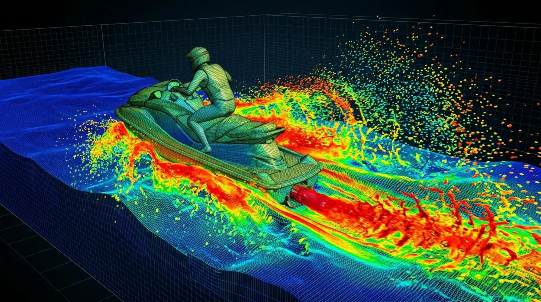
Jet Ski (Two-Phase Flow Study) — ANSYS Fluent CFD Simulation Description This project simulates the motion of a jet ski at the interface between water and air, capturing how a floating body disturbs the free surface as it moves. Flow around floating objects — boats, ships, jet skis — is one of the most common two-fluid phenomena around us, and wherever two fluids meet, the interaction and deformation of the interface becomes the central engineering question. Here the goal is to see how the jet ski rides the surface and reshapes the water behind it. Within the Marine Engineering: Beginner CFD Training Package, this project applies free-surface modeling to a fast-moving marine craft, building on the wave case toward the flow around a real floating body. Methodology The physics is handled with the Volume of Fluid (VOF) multiphase model, which tracks the sharp water–air interface as it deforms around the moving body — the standard tool for free-surface and open-channel problems where the shape of the surface is itself a key result. The computational domain has an inlet where water enters at a mass flow rate of 50,000 kg/s and a pressure outlet, with the jet ski floating at the interface. The geometry is built in ANSYS Design Modeler and meshed in ANSYS Meshing as an unstructured mesh of roughly 1,748,941 elements — unstructured here to wrap cleanly around the curved hull geometry. Analysis Post-processing provides contours of pressure and velocity, velocity vectors, and the water volume fraction. The volume-fraction field captures the free surface clearly and shows how the phases interact around the floating body — the jet ski is pushed by the flow, and a distinct wake sequence forms behind it, with water lifted above the undisturbed surface level. That surface jump is exactly the behavior you'd expect from a jet ski's interaction with the water, recovered directly from the simulation. By the end of this project, you'll be able to set up a VOF water–air free-surface case around a floating body, define mass-flow inflow and pressure-outlet conditions, and read free-surface deformation and wake structure from the volume-fraction and velocity fields.
Lesson 5 22m 14s -
Sea Robot Motion Immersed in Water (Dynamic Mesh) — ANSYS Fluent CFD Simulation Description This project presents a CFD simulation of a sea robot moving through water using the Dynamic Mesh technique — the essential method for problems where a body physically moves through the fluid domain and the computational cells must change shape and position over time. In this project, the robot (modeled as a cube) starts on one side of the domain and travels toward the inlet against an oncoming water stream, letting you study the pressure buildup ahead of it and the wake region trailing behind. Within the Marine Engineering: Beginner CFD Training Package, this project introduces dynamic mesh for a body in motion, marking the step from fixed-geometry and free-surface cases toward genuine moving-body simulation. Methodology The 2D moving-body domain is designed in Design Modeler and meshed in ANSYS Meshing with roughly 30,010 elements. Because the location and shape of the computational cells change as the body moves, a Dynamic Mesh is mandatory, and a transient solver is required. Smoothing and remeshing work together to maintain high-quality elements as the body advances, preventing the mesh degradation that causes solver errors, with the mesh regenerated at a remeshing interval of every 50 iterations. A prescribed velocity profile is imposed on the moving body — 3 m/s in the X-direction over 0–3 seconds — while the surrounding flow is set up with an inlet water velocity of 1.5 m/s using the standard k-ε turbulence model. Analysis Post-processing produces velocity, pressure, and turbulent-viscosity contours along with streamlines, revealing the elevated stagnation pressure ahead of the robot and the wake region trailing behind it. From these results you can study how the moving body loads the surrounding water and how its wake develops over time. Dynamic Mesh is the gateway to simulating real motion — submarines, AUVs, valves, pistons, projectiles, and store separation — and mastering smoothing and remeshing here equips you for an entire class of moving-body CFD problems. By the end of this project, you'll be able to set up a transient dynamic-mesh simulation, configure smoothing and remeshing to preserve mesh quality, prescribe the motion of a body through a fluid, and interpret the pressure and wake fields it produces.
Lesson 6 14m 30s -
Description This study investigates water flow over the blades of a Horizontal Axis Water Turbine (HAWT) using ANSYS Fluent, with the goal of examining the velocity and pressure distribution across the blade surfaces. Turbines of this kind are central to marine and hydrokinetic energy engineering, where they harness the kinetic energy of moving water to generate power. Two regions are defined around the blades: a cylindrical zone immediately surrounding them, and a larger domain enclosing that cylinder. In the outer domain, the water behaves as an ordinary free stream, while in the inner cylindrical region the rotational motion of the blades induces a swirling, rotational flow. Several assumptions underpin the simulation. The analysis is steady-state, since the turbine is of the horizontal-axis type and time therefore has no bearing on the drag and lift forces. A pressure-based solver is used, and gravitational force is neglected. Methodology The model was built in 3D, with the blade cross-section based on an S814 airfoil whose coordinates were taken from the Airfoil Tools website and exported as a text file. Because the airfoil section scales up or down along the blade span, Excel was used to define the coordinates at each spanwise station. Each section was then drawn in SOLIDWORKS at the appropriate angle and position and imported into Design Modeler to construct the blades and turbine shaft. Within Design Modeler, the rotational water region around the blades and the larger free-stream domain were both created. Meshing was performed in ANSYS Meshing using an unstructured grid. To improve accuracy, a boundary-layer mesh was applied to the blade surfaces, and the final cell count reached 4,270,222. The rotation of the blades is modeled using the Frame Motion (MRF) method. The turbine blades rotate at 191 rpm while the surrounding water is treated as stationary; under this approach, the blades are held fixed and the water region around them is assigned a rotating frame turning at the same 191 rpm about the Z-axis. Because the simulation is steady-state, the Mesh Motion option is disabled — it applies only when time-dependent effects must be captured, whereas here the objective is simply to impose the rotational speed on the blades. The solution setup is summarized below: Viscous model — SST k-omega Boundary conditions — velocity inlet at 1 m/s; pressure outlet at 0 Pa gauge; all walls set as stationary Solution methods — SIMPLE pressure-velocity coupling; second-order upwind discretization for pressure, momentum, turbulent kinetic energy, and turbulent dissipation rate Initialization — standard method, with an initial velocity of −1 m/s in the Z-direction Conclusion On completion of the solution, the velocity and pressure distributions over the turbine blades can be examined in detail through the corresponding contours. These results reveal how the water loads the blade surfaces and how the rotational flow develops within the cylindrical zone, providing the basis for evaluating the hydrodynamic performance of the horizontal-axis water turbine.
Lesson 7 12m 48s -
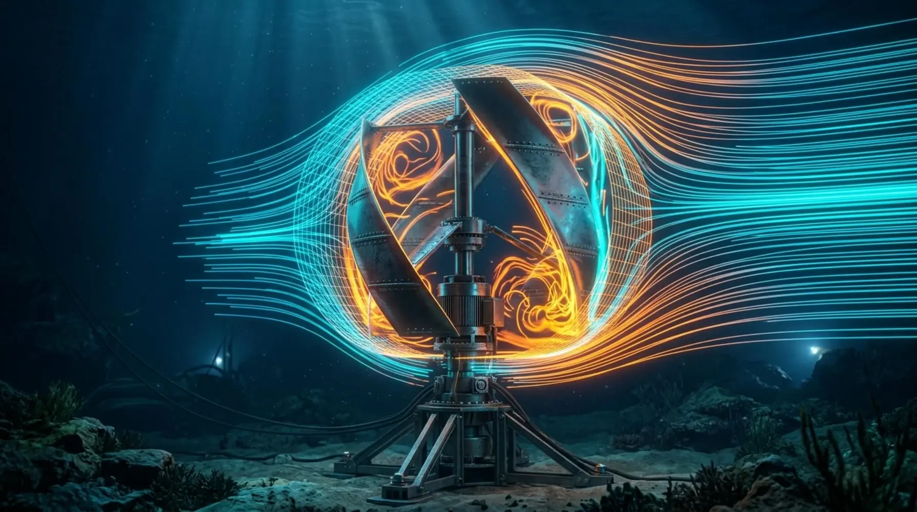
Description This project uses ANSYS Fluent to simulate a Darrieus-type vertical axis water turbine (VAWT) submerged in flowing water, applying the Dynamic Mesh method to capture rotation driven by the surrounding flow — a relevant application in marine renewable energy and hydrokinetic power generation. Unlike wind-based VAWTs, this turbine extracts kinetic energy directly from water flow, with its rotational axis perpendicular to the flow direction. The three-bladed turbine rotates freely in response to the fluid forces acting on it, allowing its performance under water flow conditions to be evaluated. Methodology The 3D geometry is built in DesignModeler, consisting of a large computational domain containing a three-bladed Darrieus turbine (0.5 m blade height), with the turbine center positioned 3 m from the inlet, 10 m from the outlet, and 0.75 m from the top and bottom domain surfaces. The domain is meshed in ANSYS Meshing using a hybrid grid — unstructured around the turbine body and structured elsewhere — totaling 7,422,668 elements. Water enters the domain at 1 m/s along the horizontal axis, with a pressure outlet at atmospheric conditions and symmetry conditions applied to the top and lateral surfaces. The turbine's rotation is captured using the Dynamic Mesh model, with a cylindrical sub-region isolating the turbine blades as rigid bodies. Rotational motion is defined with one degree of freedom (1-DOF), using a blade mass of 1 kg and moment of inertia of 3.09 kg·m². The simulation is run transient, over 50 seconds with a 0.05 second time step, consistent with the dynamic mesh approach. Conclusion Results include 2D contours of velocity, pressure, and turbulent kinetic energy, along with pathlines and velocity vectors on a plane through the turbine center. Turbine torque and other performance characteristics are also analyzed, providing insight into the turbine's power extraction behavior — relevant to marine hydrokinetic energy system design and evaluation.
Lesson 8 16m 17s -
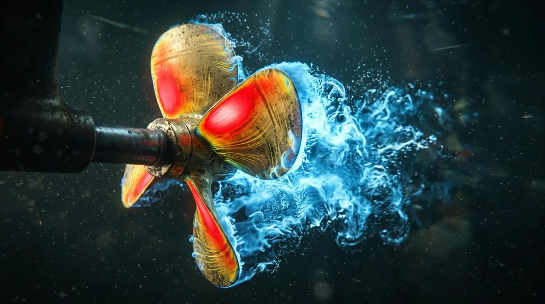
Description This project uses ANSYS Fluent to simulate boat propeller cavitation, applying the Mixture multiphase model to a critical phenomenon in marine propulsion engineering. Cavitation occurs when localized low pressure on the propeller blades causes water to vaporize, forming bubbles that collapse and erode blade surfaces while degrading propulsion efficiency. This simulation captures how cavitation forms and evolves around a rotating propeller, a key concern in naval architecture and propeller design. Methodology The propeller geometry is built in DesignModeler and meshed in ANSYS Meshing using an unstructured grid suited to the rotating fluid domain. The Mixture model is configured with the Schnerr-Sauer cavitation model to simulate water-vapor phase change, with appropriate vaporization pressure limits set to capture cavitation onset. Mesh motion is implemented to represent propeller rotation, paired with the SST k-omega turbulence model for accurate external flow resolution, and the analysis is run transient to capture the time-dependent development of cavitation, including super-cavitation at high rotational speeds. Conclusion Results include vapor volume fraction distributions on the propeller surfaces, pressure fields showing where cavitation initiates and grows, and the relationship between rotational speed and cavitation extent. These findings directly inform propeller design optimization — blade geometry, material selection, and operating speed — to reduce cavitation-driven erosion, noise, and vibration, supporting more efficient and durable marine propulsion systems.
Lesson 9 1h 6m 3s -
Description This project extends a previous simulation of the VA-111 Shkval supercavitating torpedo in ANSYS Fluent by incorporating mass transfer to capture cavitation effects. The objective is to analyze how cavitation influences the vehicle's hydrodynamic performance and to compare it against the non-cavitating case. The Shkval is a high-speed underwater vehicle, making this a distinctly marine and naval engineering problem, where supercavitation is exploited to dramatically reduce drag and enable exceptional underwater speeds. The geometry and mesh remain the same as in the previous study: the VA-111 Shkval was created in SpaceClaim and meshed in Fluent Meshing, producing a polyhedral mesh of 257,000 cells. Methodology The simulation uses a transient, pressure-based solver with the k-ε turbulence model, initialized from a steady, no-mass-transfer case. To capture the cavitation, the Zwart-Gerber-Belamri model is enabled, which accounts for the mass transfer between the liquid and vapor phases. This cavitation model is coupled with the VOF multiphase model to accurately represent the formation and collapse of the vapor cavities that surround the vehicle. Conclusion The results reveal significant differences in the flow field and performance characteristics once cavitation is taken into account. The mass transfer rate contour identifies the regions where cavitation occurs, with the highest rates near the vehicle's nose and along its body. The volume fraction contour shows the vapor cavities enveloping the vehicle, which effectively reduce the wetted area. The pressure distribution exhibits a low-pressure region near the nose that triggers the formation of the vapor cavities, and the velocity magnitude contour shows higher velocities within the cavity than in the surrounding liquid — confirming the drag-reduction mechanism of supercavitation. The turbulent kinetic energy contour highlights elevated turbulence in the wake, caused by the collapse of the vapor cavities; this turbulence can add to the drag and affect the vehicle's stability. Overall, incorporating mass transfer and cavitation modeling provides valuable insight into how cavitation shapes the hydrodynamic performance of the VA-111 Shkval. The results clearly demonstrate the benefits of supercavitation: by forming vapor cavities that shrink the wetted area, the vehicle achieves a marked reduction in skin-friction drag — the key principle behind high-speed underwater travel in marine engineering.
Lesson 10 9m 59s
Beginner Marine CFD Course: Ship, Turbine & Cavitation Projects
Marine and offshore engineering brings together some of the most challenging problems in fluid dynamics. Free-surface waves, bodies moving through water, and hydrodynamic loading on submerged structures require specialized simulation approaches.
This beginner marine CFD training turns that broad field into a structured, confidence-building path. You will complete ten carefully sequenced Ansys Fluent projects designed for naval architecture. These tutorials take you from your first ship-system simulation to genuinely advanced cavitating flows. As a trusted CFD Course provider, we ensure you learn by building real simulations rather than just watching theory.
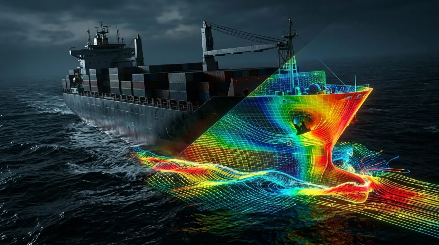
The package is ordered deliberately to build your skills incrementally. You begin with the ventilation system of a ship's engine room, a self-contained internal-airflow problem. From there, you move to hydrodynamic forces on an offshore pipeline before stepping into free-surface modeling. By the end, you will have practical, repeatable experience across the core scenarios of marine engineering.
Software Requirements: Which Solvers Does This Course Cover?
Looking for marine CFD software downloads? This page is for our comprehensive training course on how to use industry-standard solvers for marine applications. We focus exclusively on Ansys Fluent for these step-by-step tutorials.
When comparing tools, Ansys Fluent handles the VOF (Volume of Fluid) method for sea waves efficiently. Other tools like Star-CCM+ have their own marine modules, but Fluent provides an accessible, robust environment for beginners. If you need to scale these complex multiphase simulations, our ANSYS HPC service resources can drastically reduce your solution times.
Course Syllabus: 10 Marine CFD Projects
Below is the complete sequence of projects included in this marine engineering package. Each tutorial is self-contained, covering geometry, meshing, setup, solution, and results interpretation.
1. Ship Engine Room Ventilation System
You will start by simulating thermal comfort and ventilation in a ship engine room. This internal airflow problem introduces the standard CFD workflow. It focuses on heat transfer and duct sizing.
Key concepts: Internal airflow, thermal management, k-epsilon turbulence model.
2. Offshore Pipeline: Hydrodynamic Force
Next, you will analyze hydrodynamic forces on an offshore pipeline. Water flowing past a fixed submerged body creates vortex shedding. You will calculate drag and lift coefficients.
Key concepts: External flow, drag/lift calculation, vortex shedding.
3. Floating Solar Panel
This project steps into the defining feature of marine CFD: the free surface. You will simulate a floating solar panel using the Volume of Fluid (VOF) method. This tracks the water-air interface accurately.
Key concepts: VOF multiphase, free-surface tracking, buoyancy.
4. Sea Short Waves
Building on your VOF knowledge, you will simulate sea short waves. This is crucial for evaluating how structures respond to wave loading. You will apply specific wave boundary conditions.
Key concepts: Wave generation, open channel flow, VOF.
5. Jet Ski: 2-Phase Flow
You will then apply free-surface modeling to a fast-moving marine craft. The jet ski two-phase flow VOF simulation captures the complex wake and spray patterns. It introduces dynamic fluid body interaction.
Key concepts: Dynamic fluid body interaction, overset mesh, high-speed craft.
6. Sea Robot Motion Immersed in Water: Dynamic Mesh
The second half of the package introduces motion. You will use dynamic mesh for sea robot motion. This captures the body's movement through the fluid domain using smoothing and remeshing methods.
Key concepts: Dynamic mesh for sea robot motion, 6-DOF solver, UDFs.
7. Water Turbine: Horizontal Axis
You will begin exploring marine energy extraction with a horizontal axis marine turbine. This project teaches you how to use the sliding mesh approach. You will analyze torque and power output.
Key concepts: Hydro-kinetic water turbine CFD, sliding mesh, rotational zones.
8. Darrieus Water Turbine: Vertical Axis, Dynamic Mesh
Next, you will model a Darrieus vertical axis open-water turbine. This utilizes dynamic mesh to capture its rotation. It demonstrates how to extract energy from tidal currents.
Key concepts: Dynamic mesh Darrieus turbine, vertical axis turbines, unsteady simulation.
9. Boat Propeller Cavitation
The final two projects cover cavitation. You will simulate boat propeller cavitation multiphase flow. This captures the phase change and vapor formation around the propeller blades.
Key concepts: Boat propeller cavitation multiphase, Schnerr-Sauer model, rotating machinery.
10. VA-111 Shkval Rocket: Supercavitation Inject, Mass Transfer
The capstone project is the VA-111 Shkval rocket supercavitation mass transfer simulation. You will model how injecting gas forms a vapor cavity around a high-speed underwater body.
Key concepts: Supercavitation mass transfer, high-speed compressible flow, gas injection.
Core CFD Techniques You Will Master
Throughout these Ansys Fluent marine CFD projects for naval architecture students, you will master several critical techniques. These skills are directly transferable to real-world engineering applications.
Volume of Fluid (VOF) for Marine Applications
You will extensively use the VOF model to track the interface between water and air. This is essential for simulating floating solar panels, sea waves, and jet ski spray.
Dynamic Mesh and Sliding Mesh
You will learn the difference between dynamic mesh and sliding mesh. The course applies dynamic mesh for sea robot motion and sliding mesh for water turbines.
Cavitation and Mass Transfer Modeling
You will conquer cavitation, one of the most difficult phenomena in marine engineering. You will simulate both standard boat propeller cavitation and advanced supercavitation.
Who Should Enroll in This Marine Engineering Package?
This package is ideal for students, interns, and engineers seeking a solid, application-first foundation. If you need step-by-step Ansys Fluent marine hydrodynamics tutorials, this course is built for you.
Engineers looking to transition into naval architecture will find this training particularly valuable. It bridges the gap between theoretical fluid dynamics and practical software application.
Prerequisites and Next Steps
To succeed in this course, you should have basic computer literacy and a fundamental understanding of fluid mechanics. If you are entirely new to the software, we recommend completing our Ansys fluent beginner course first.
Once you complete this beginner marine CFD training, you will be ready to tackle more complex simulations. You can advance your skills by enrolling in our Ansys fluent intermediate course to master advanced turbulence models and complex geometries. For those aiming for expert-level proficiency, the Ansys Fluent Advanced Course is your next destination.
Career and Professional Application
The skills learned here directly translate to industry demands. Many of our graduates use these tutorials to prepare for a CFD Internship or to bolster their portfolios.
If you are a professional facing a complex marine project, MR CFD offers specialized support. You can also leverage our CFD Consulting services for immediate, expert-level project assistance.
Start your journey into marine CFD today and build the skills needed to excel in offshore and naval engineering.
This package includes 10 hands-on Ansys Fluent tutorials covering ship engine ventilation, offshore pipelines, floating solar panels, sea waves, jet skis, sea robots, horizontal and Darrieus water turbines, and propeller cavitation.
You will use the multiphase mixture model with the Schnerr-Sauer cavitation model in Ansys Fluent to capture the phase change and vapor formation around the propeller blades.
Both solvers are industry standards. Ansys Fluent is excellent for VOF sea wave tracking and dynamic mesh setups, while Star-CCM+ is heavily favored for naval hydrodynamics. This course focuses entirely on Ansys Fluent.
The first project teaches you to model internal airflow and thermal distribution using standard k-epsilon turbulence models to ensure adequate cooling and ventilation in the engine room.
The course covers dynamic mesh techniques specifically for sea robot motion, utilizing smoothing and remeshing methods to capture the body's movement through the fluid domain accurately.
Yes. You will learn to calculate drag and lift coefficients on a submerged offshore pipeline, focusing on boundary layer separation and hydrodynamic loading.
You will use the sliding mesh technique alongside dynamic mesh to capture the rotation of the Darrieus turbine, analyzing torque and power extraction from marine currents.
The final project models supercavitation by combining the multiphase VOF model with mass transfer mechanisms, simulating the high-speed rocket injecting gas to form a vapor cavity.
You will use the Volume of Fluid (VOF) multiphase model in Ansys Fluent to track the water-air interface and apply appropriate wave boundary conditions to generate sea short waves.