Reach Professional-Grade ANSYS Fluent Training Course — Ep 05
Chemical: Plasma Gasification Reactor
- Lesson
- 05
- Run Time
- 10m 39s
- Published
- Jun 24, 2026
- Category
- ANSYS Fluent
- Course Progress
- 0%
Plasma Gasification Reactor — ANSYS Fluent CFD Simulation
Plasma gasification is a high-temperature waste-treatment process that converts organic material into synthetic gas (syngas). An electric arc generates plasma hot enough to ionize and break down the feedstock, leaving behind syngas and an inert solid residue. It's used to treat waste and to process biomass and heavy hydrocarbons such as coal and petroleum sands — turning low-value or hazardous material into usable fuel gas. This project uses ANSYS Fluent to simulate the airflow and heat distribution inside such a reactor, capturing how the hot inlet streams behave as they meet and rise toward the outlet.
The reactor is modeled in two dimensions in Design Modeler as a symmetrical chamber with two inlets — one on each side — and a single outlet along the top edge. The domain is meshed in ANSYS Meshing with a structured grid of 8,711 elements.
The simulation captures the thermal-flow behavior of the reactor. Hot gas enters through the two side inlets at 0.1 m/s and 2000 K, and leaves through the top outlet at atmospheric pressure. The reactor's side walls are held at a fixed temperature of 600 K, representing heat loss through the chamber boundary. Running the case to convergence resolves how the two opposing inlet streams interact and how heat is carried through the chamber.
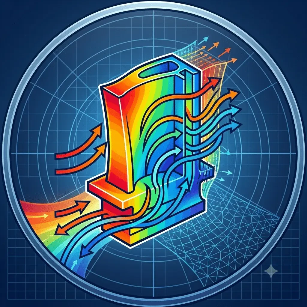
At the end of the solution, you generate 2-D contours of pressure, velocity, and temperature, along with path lines and velocity vectors. The pressure drops as the flow approaches the outlet. The maximum velocity appears at the center of the chamber, where the two inlet streams collide and merge, while the highest temperatures sit at the inlets, where the hot 2000 K gas enters before mixing and cooling toward the walls. By the end of this project, you'll be able to set up a thermal-flow simulation with multiple opposing inlets, apply fixed-temperature wall conditions, and interpret how colliding streams shape the velocity and temperature fields inside a reactor.