Reach Professional-Grade ANSYS Fluent Training Course — Ep 01
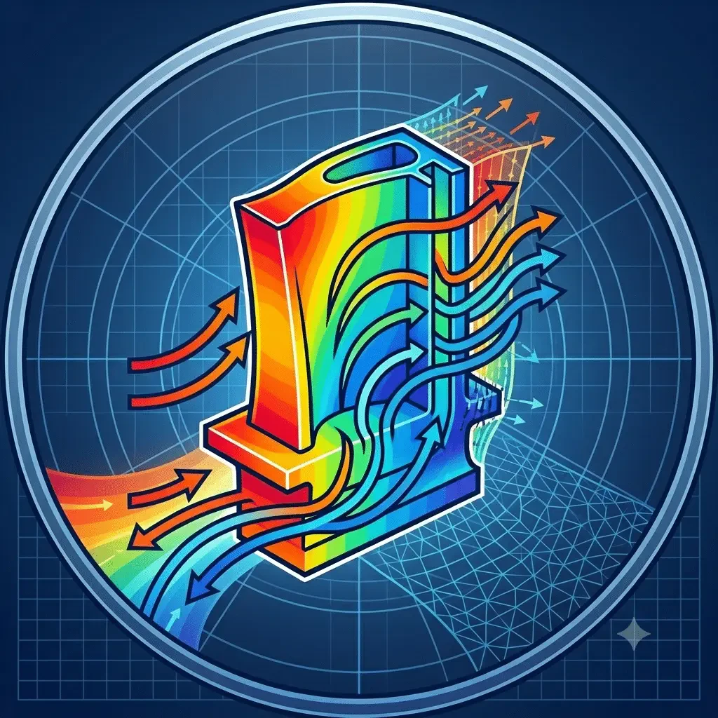
Chemical Reactions: Vortex Flame Combustion Chamber with Four Inlets
- Lesson
- 01
- Run Time
- 15m 54s
- Published
- Jun 25, 2026
- Category
- ANSYS Fluent
- Course Progress
- 0%
Vortex Flame Combustion Chamber, 4-Inlet (Methane and Air) — ANSYS Fluent CFD Simulation Training
This project simulates the vortex flame inside a combustion chamber using ANSYS Fluent, with the full case analyzed through CFD post-processing.
The geometry is a three-dimensional cylindrical combustion chamber built in Design Modeler. Air enters through four inlet sections arranged radially around the chamber, while fuel enters through four inlet sections positioned axially at the top. A single outlet at the bottom of the chamber discharges the combustion products.
The mesh was generated in ANSYS Meshing using a structured grid, with a total of 725,521 elements.
Methodology
The chamber has a cylindrical structure in which the reactants — fuel and air — enter separately through four inlets in the upper region, and the reaction products exit from the bottom.
Air enters radially through four inlets spaced 90 degrees apart around the outer circumference of the chamber, while methane is injected directly into the chamber interior through the remaining four inlets. This arrangement establishes the swirling, vortex-shaped flame at the heart of the model.
The chemical reaction between air and methane is modeled with the Species Transport model, involving five species: O₂, N₂, CH₄, CO₂, and H₂O. The incoming air contains a mass fraction of 0.23 oxygen, with a flow rate of 0.001135845 kg/s at 300 K. The fuel enters simultaneously at a flow rate of 0.0000645 kg/s, also at 300 K.
The outer wall is treated as a convective boundary exchanging heat with the surroundings, with an ambient (free-stream) temperature of 300 K and a heat transfer coefficient of 25 W/m²·K.
The RNG k-epsilon turbulence model and the energy equation are both activated to resolve the turbulent flow field and compute the temperature distribution throughout the domain.
Results
The solution yields 2D and 3D contours of pressure, temperature, velocity, and the mass fractions of O₂, CH₄, H₂O, CO₂, and N₂.
The contours show that as combustion takes place between fuel and air, temperature rises sharply near the chamber inlets. As the reaction proceeds, the methane mass fraction decreases while the mass fractions of the combustion products — CO₂ and H₂O — increase accordingly.